
Allan
M Gardner
Oxfordshire-based Music Electronics Engineer
Oxfordshire-based Music Electronics Engineer
|
Allan
M Gardner Oxfordshire-based Music Electronics Engineer |
| Ampeg
Portaflex B-15NB  |
||
| This bass amplifier combo dates from 1964 and has a sweet, sought-after tone. This particular example was brought in for repair, with the symptoms described as, “It was humming a bit and then it died altogether. | ||
 |
 |
|
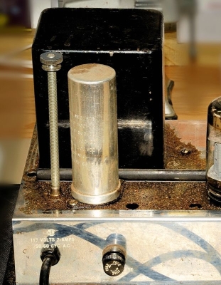
| First
impressions were that it had a lot of contamination around the top of the
amplifier chassis, with some evidence around the base and screws. |
||
| The amplifier chassis is fixed to the ‘flip-top’ lid of the cabinet with two bolts, (already removed in the above photographs). By removing these bolts the chassis should simply lift off the lid of the cabinet, but in this case it was not possible to lift the end of the chassis with the power transformer at all, and the other end, holding the output transformer, could only be lifted 1 or 2 centimetres. Shining a torch into the gap between the lid and the chassis revealed that wax had melted onto the circuit components and then solidified, effectively fixing the chassis to the lid. | ||
| It
could be seen that lifting the chassis any further would put undue strain
on the components, wiring, and eyelet board, so I decided that the wax needed
to be heated whilst at the same time gently lifting the chassis away from
the lid. I placed two hair-driers so that the hot air was blowing into the cavity, whilst at the same time I gently lifted the chassis. After almost an hour the chassis could be lifted sufficiently to allow a 12" steel ruler to be pushed between the lid and the mass of wax so that the lid could safely be removed completely. |
 |
|
It
was now obvious that the wax was the potting insulation from the power-transformer,
which had failed catastrophically. Before any circuit fault-finding could
be done, there was a big clean-up job that needed doing first! |
 |
|
|
Helpfully the lid of this amplifier contains a circuit diagram, although in this case it wasn’t as legible as it could have been! |
 |
|
After removing this ball of wax:- |
 |
|
| I could now get a first look at the circuit:- | ||
 |
||
|
Although
the clean-up operation would continue for some time, I could now get a
better look what had been the main cause of the failure, along with anything
else that needed doing. |
 |
|
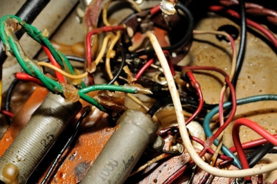
| Worryingly, some of the unused connections to the transformer were very poorly terminated, if at all. |  |
|
| There
were some other examples of poor wiring, as shown in the following... Some insulating-tape wrapped around a speaker connection was hiding an almost-severed wire: |
||
 |
 |
|
The other speaker connection wasn’t in very good shape either: |
 |
|
| The mains lead and plug was wired with 4-core rubber-insulated cable. The rubber had begun to perish and the extra, unused wire was snipped off and left uninsulated. |
 |
|
The main cause of the power transformer failure was due to the power-supply multi-section electrolytic capacitor having failed. This was a 40x40x40x40 µF / 500V capacitor which is under considerable stress whilst it filters the HT. The first section was found to be short circuit, which would have placed an enormous load on the power transformer, and the third had a higher than usual ESR (>20 Ohms), which would have considerably reduced its filtering capability. |
||
 |
 |
|
|
An exact replacement was not recommended, as this was known to be a cause of failures, so a 40x40x40 µF / 525V along with a separate 30µF / 600V to replace the first section was substituted. The original multi-cap is shown on the left, The new multi-cap is shown on the right. |
||
| Finding space for the extra 30µF / 600V capacitor was a challenge, but room was made near the rear-panel fuse-holder, which I had substituted for a 20mm type instead of the stock 1¼", which was not in good condition. |  |
|
| Obviously, the power-transformer, (PT), had to be replaced, and to gain access I needed to lift the eyelet board out of the way. This required that all of the wiring from the board had to be un-soldered, and the board carefully lifted out of position. This gave access to the PT fixing nuts and also allowed the rest of the wax to be cleaned from out of the chassis tray. | ||
 |
 |
|
After replacing
the PT, power-supply multicap, and bias-capacitor I embarked on making
the wiring safe. I used the spare 5V secondary on the transformer, (unused
in this solid-state rectifier model), to power the plexi-glass logo illumination.
These bulbs are normally wired across the 6.3V valve heater supply, but
by separating them to the spare 5V supply it reduces the heater load and
also extends the life of the bulbs. A fresh pair of bulbs and new plexi-glass
logo freshens up the appearance. |
||
 |
||
| Finally, a little gift for any future engineers that look inside this amp .. fully marked up with test voltages, and the 240V power transformer wiring. |
 |
|
It
now sounds like it should! |
|
|
with
grateful thanks to Bruce Michielli of fliptops.net for his invaluable
advice. |
||