
Allan
M Gardner
Oxfordshire-based Music Electronics Engineer
Oxfordshire-based Music Electronics Engineer
|
Allan
M Gardner Oxfordshire-based Music Electronics Engineer |
| Fender Vibrolux Reverb  |
||
| This
amplifier was brought in for repair after having had Mark Moyer modifications
supplied as a kit by Fromel Electronics. The object of the modification
was to remove the original hiss, sometimes present on this particular model.
In the modification Reverb is removed from the ‘Normal’ channel,
Tremelo was left on, negative feedback was introduced, a bias control added,
and a general re-cap, mainly to the PSU and Tonestack. The kit had been fitted to the amp prior to it coming into my workshop, but the client complained there was lots of noise on Normal channel and some on the Bright. He was reluctant to return the amplifier to the engineer that did the original work. When the amp was opened up the first impression was that there was damage to some of the printed circuit board (PCB) tracks and pads. As investigations progressed it became apparent that there were a great number of damaged tracks and pads. Wherever components, wires or jumpers had been removed from the PCBs there seemed to be more tracks/pads damaged than not. |
||
| The
bias control that had been added used a 10k resistor in series with a
100k potentiometer to replace the original 18k resistor at R59. R58, on
the Tremelo daughter board, had been changed from 2k7 to 1k. I felt that
the 100k pot was an odd choice, being of an excessively high value, but
noted that it had been adjusted all the way to zero; perhaps proving the
point. |
 |
|
More worrying was the standard of work in adding this mod. In removing R58 the PCB pads and track had been badly damaged, and the resistor replacement not done at all well. |
||
 |
 |
|
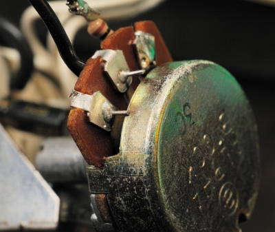
| The
wiring to the pot was also very poorly done, with the very real danger of
reducing the bias to the output valves to zero, an effective way of blowing
the valves. Note that the wire which is almost touching the potentiometer case will be at a potential of approximately -50 Volts relative to ground. |
 |
|
| I repaired the tracks/pads, replaced R59 with a series 10k resistor and 50k/15turn pot, to allow precise control), and reinstated R58 to 2k7. |  |
|
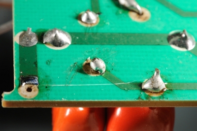
| During the modification to the reverb circuit, C16 had been replaced and, yet again, the PCB damaged. | ||
 |
 |
|
| In this case a repair had been implemented by adding a jumper wire from the capacitor to the destination point of the PCB track. (This wire is connected to the anode of V4a, and would normally carry in excess of 200V as well as the recovered reverb signal). | ||
I
removed the jumper wire and repaired the PCB to a more acceptable standard. |
 |
|
| The HT smoothing capacitors had been changed, unfortunately to much the same standard... | ||
 |
 |
|
| In
this case the PCB pad had been damaged and the capacitor lead soldered to
the remaining track, but without cleaning off the solder resist first, leaving
a very poor solder joint. The tonestack modifications to the Normal channel were very much in line with the standards already noted, but perhaps the worst of all. |
||
 |
 |
|
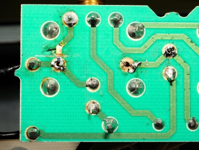
| Once
again wires had been ‘soldered’ to damaged tracks without prior
removal of solder resist. Removing the solder revealed the full extent of
PCB damage. (Note the soldering iron score mark from the damaged bottom right PCB pad.) |
 |
|
| After
much re-work the excessive noise apparent on the Normal channel was finally
narrowed down to the 330pF capacitor (C2*) on the Normal channel control
daughter-board. This was yet another case of bad de-soldering, damage to
the tracks, and re-soldering of the new component.
I would estimate that the original modifications should
take approximately 3 to 4 hours in the hands of a competent technician,
but the extensive inspection and re-work caused by unprofessional engineering
took nearer 20 hours. (Note that the photographs above show only a few representative
problems found in this amplifier; they do not show every example found.) |
||